
I Type Fin Tube|Tension Wound Finned Tube

I Type Fin Tube|Tension Wound Finned Tube

The fin strip is tension wound onto the base tube. Typical fin materials: carbon steel, stainless steel, copper, brass and copper-nickel
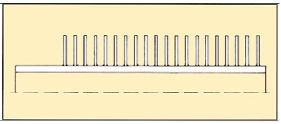
I Type Fin Tube Size Range:

Base tube size: 6-219.1 (other sizes upon request)

Fins: 50-500 fins/meter

Fin thickness: 0.2-1.5 mm

Fin quantity and size depend on diameter of base tube. In case of deviation against the sizes of the opposite page, please ask us.

Tolerances: Fin height: +/- 1mm

Fins/meter: +/- 2%

Plain ends: +/- 5mm

I Type Fin Tube Fields of Application:

Climatic Industry, Cooling, Heating, Drying

I Type Fin Tube Manufacturing Process

For I type fin tube, the fins are spirally wound on a base tube, without welding, just fin spot welded. Non ferrous tubes and fins on either

root soldered or completely tinned

Execution: black, galvanized and for special applications

Stainless Steel, Copper, Brass, and/or Aluminium.

Ends can be bevelled, bended upon request.
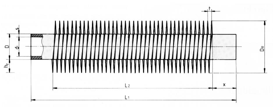
I Type Fin Tube drawing

In order to forward you a promt offer we would be pleased to receive you detailed enquiry containing:

• Base tube material and quantity

• Base tube size

• Fin material

• Fin type

• Fin diameter or height

• Fin thickness

• Fins per inch, meter or fin pitch

• Lenght of plain, unfinned ends (nessesary to roll or weld the tubes into tubeplate or assembly)

Comments

Popular posts from this blog

What is membrane water wall panel?

What is membrane water wall panel? The Membrane water wall pane l is the main heating part of the boiler, which is composed of several rows of steel tubes, distributed around the boiler furnace. Its interior is flowing water or steam, and the outside receives the heat from the flame in the boiler furnace. It mainly absorbs the radiant heat of high-temperature combustion products in the furnace, in which the working medium rises and evaporates. Membrane water wall panel refers to the water wall composed of a gas tight pipe panel welded by flat steel and tubes. The membrane water wall can ensure the furnace has good tightness and can significantly reduce the air leakage coefficient of the furnace and improve the combustion conditions in the furnace for negative pressure boilers. The utility model can increase the effective radiation heating area, thereby saving the steel consumption. Advantages of Membrane water wall panel (1) The membrane water wall has the most complete protective effe...

What are the components of finned tube bundle?

The heat exchange unit composed of multiple finned tubes arranged according to certain rules is called finned tube bundle. A finned tube heat exchanger can be composed of one or more finned tube bundles. Understanding the finned tube bundles is helpful to the application of finned tube heat exchangers.   What are the components of finned tube bundle?   1. Multiple finned tubes: basic elements of heat transfer;   2. Tube box header or tube plate: connect the box, elbow or steel plate at both ends of the finned tube. When the finned tube is connected with the box or tube plate, the spacing between the finned tubes is fixed, and the tube box makes the fluid in the tube form a continuous flow channel;   3. Frame: support and fix the whole finned tube bundle.   The finned tube bundle is the main part of the air cooler, which is composed of finned tubes, tube boxes and frames. It is an independent structural whole. Its basic parameters include the tube bundle type (us...

What is tube sheet layout?

What is tube sheet layout? A tube sheet is a component used in shell and tube heat exchangers and other types of heat transfer equipment. It is a flat plate with holes drilled in it, through which tubes are inserted and secured. The tube sheet serves as a barrier between the two fluids, allowing heat to be transferred from one to the other. The layout of the tube sheet depends on the design of the heat exchanger, which includes the number of tubes, the size of the tubes, and the spacing between the tubes. The layout is typically determined using computer-aided design (CAD) software, which can optimize the placement of the tubes to achieve the desired heat transfer performance. In general, the tubes are arranged in a triangular or square pattern on the tube sheet. The triangular pattern is often preferred because it provides better support for the tubes and reduces the risk of vibration and damage. The spacing between the tubes is also important, as it affects the flow rate and pressure...